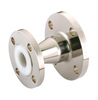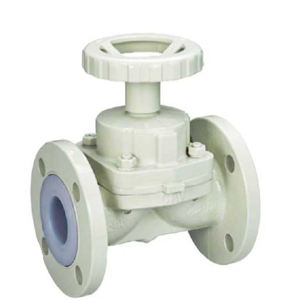
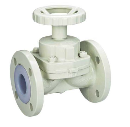
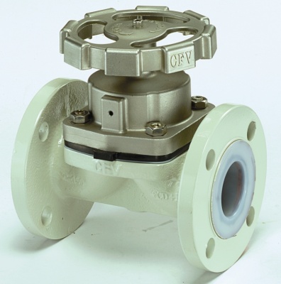
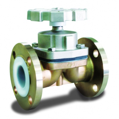
Diaphragm Valve Carbon Steel PFA Lined – PD-31W PN16 – Bueno
Specification
Size Range DN15~DN100
Pressure grade PN16
Operating temperature -30°C ~+120°C
Valve body design EN 12516
- Maximum operating pressure
- DN15-DN25 14kgf/cm^2 (200psi)
- DN40-DN50 12.3kgf/cm^2 (175psi)
- DN65-DN100 10.5kgf/cm^2 (150psi)
Joints : EN 1092-1
Face to face EN-588-1
Material List
| Designation | Material |
| BODY | 1.0619+PFA Lined |
| BONNET | 1.0619 |
| HANDLE | 1.0619 |
| STEM | SS304 |
| DIAPHRAGM | PTFE |
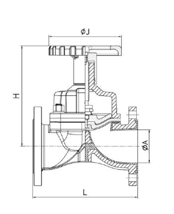
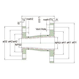
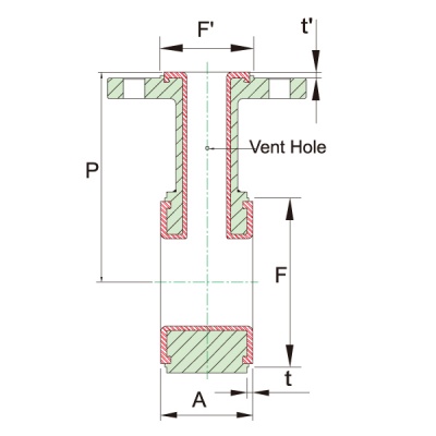
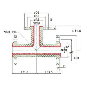
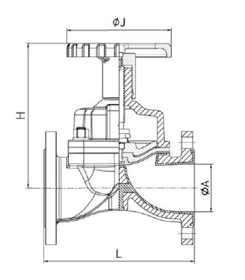
Dimensions
| SIZE | ØA | H | J | L | |
| in | mm | PD11 | PD51 | ||
| 1/2″ | 15 | 15 | 100 | 100 | 130 |
| 3/4″ | 20 | 19 | 103 | 100 | 150 |
| 1″ | 25 | 25 | 108 | 100 | 160 |
| 1-1/2″ | 40 | 40 | 153 | 120 | 200 |
| 2″ | 50 | 50 | 168 | 120 | 230 |
| 2-1/2″ | 65 | 65 | 226 | 180 | 290 |
| 3″ | 80 | 80 | 237 | 180 | 310 |
| 4″ | 100 | 100 | 320 | 230 | 350 |
Construction Drawing
Produits similaires
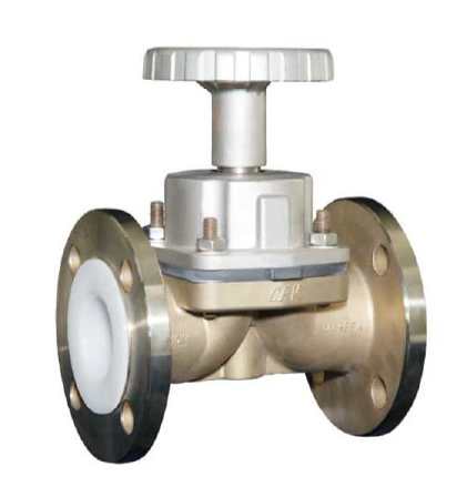
Diaphragm Valve Stainless Steel PFA Lined – PD-31 PN16 – Bueno
Thursday August 30th, 2018
Diaphragm Valve Carbone Steel – PD-11W CLASS 150 LB – Bueno
Thursday August 30th, 2018
PFA Lined Diaphragm Valve JIS 10K – Bueno
Sunday August 19th, 2018
Diaphragm Valve Stainless Steel PFA Lined – PD11 CLASS 150 – Bueno
Thursday August 9th, 2018